Latest News

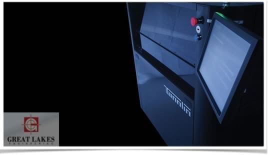
Great Lakes Engineering installs the most powerful T11 yet.

T11 Tannlin Laser System

Great Lakes Engineering, one of the USA's foremost precision laser parts and stencils manufacturers recently took delivery of the most advanced Tannlin laser system ever. The new machine boasts a 300W fiber laser with the ability to cut thicker materials at a faster rate.

For Great Lakes customers, the installation of the machine will see more accurate multilevel stencils than ever before, with the TML Tannlin multi level function

In addition to the 300W laser, the upgraded machine features an adjustable chase to accept stencils sized from 400mm to 850mm. The new feature will give Great Lakes the scope to comfortably cut a more extensive range of designs and sizes - the Great Lakes T11 has the ability to cut 1.8 meters (70”) in length. The Tannlin MultiLevel (TML) function which works purely through laser cutting and micro welding, leaves the surface of the steel unaltered. Therefore, TML (Tannlin MultiLevel) stencils feature the same perfect print you see on our single level stainless steel stencils with no compromise.


The Various Steps Involved in Metal Etching Explained

Metal etching, also called chemical milling or chemical machining, is a frequently used, highly valuable subtractive industrial process that uses any number of etching chemicals, called etchants, to achieve a desired metal embellishment or shape. This process dates back to feudal times, when proud lords and knights used it to decorate their armor.

During the metal etching process, a metal sheet is covered in a masking compound in a predetermined way, and the metal is bathed in a corrosive chemical known as an etchant. The etchant chemically reacts with the exposed material, without any masking material, and cuts the exposed material by dissolving it. The masking compound is usually inert. This process is also known as chemical milling or chemical machining.

With metal etching, cuts with varying depth are achieved, and the depth is determined by the time spent by the material in bath. The rate of etching is defined by the ratio of depth of cut to time spent in the bath. Many factors, such as the material to be etched, temperature, the etchant composition and concentration determine the rate. As there are number of factors that can influence etching, the common practice is to do a test run, where a material is exposed to chemicals and monitored for output performance. Based on the process performance, the chemistry and test are repeated until a desired depth and rate are achieved.

The standard metal etching process follows several specific steps to ensure an optimal outcome. This outcome involves the careful calculation of the rate of etching, which is based on several factors, including temperature, the material being etched, etchant composition and concentration. To understand the standard metal etching process, study the steps listed below.

Step 1: Clean Surfaces

Before doing anything else, you must clean your surfaces. Ensure that no contaminants, which can alter the reaction and result inconsistent etching, remain. These contaminants are usually things like grease, oils, primer coatings and residue. To remove them from metal surfaces, use solvents, specifically oxidizing and alkaline solutions.

Step 2: Apply Masking Agent

Generally, masking agents, or maskants, selected for use in industrial settings are inert in nature, meaning that they maintain their structural integrity during chemical reactions. Such maskants include neoprene elastomers and isobutylene-isoprene copolymers. In the second step of metal etching, known as the masking stage, you apply these maskants to your surface in such a way to produce the pattern you want. You can do this either through dip masking, or immersing the parts into the maskant, or by flow coating, when you allow the maskant to flow over the parts.

Masking cn dip masking, the parts are immersed into maskant, whereas in masking by flow coating, the parts are coated by flowing the solution over a surface.

Step 3: Immerse in Etchant

The third step is immersion, the step during which a chemical reaction takes place. Let the parts remain in the corrosive material for a predetermined period of time, chosen to achieve your desired width.

Step 4: Remove the Mask

Remove the products of reaction and demask the surface of your metal to uncover the design and pattern you’ve created. To fully removed etchants, use methods involving cold water, like de-oxidizing baths, which remove leftover oxides. Typically, cold water is used for specific etchants and specialized processes, such as a de-oxidizing bath. In turn, remove maskants manually with scraping tools.
The Differences between Dry and Wet Etching

Metal etching, a technique used to, as its name suggests, etch designs into metal, can be either dry or wet. This dry or wet state is determined by the etchant used to dissolve the metal. Etchants used are frequently chemicals, but etching via chemicals is not to be confused with chemical milling, a similar but less effective process.

In addition to being dry or wet, etching can be anisotropic, when an enchant removes material vertically, or isotropic, when an enchant removes material uniformly in all directions. Also, anisotropic etching may be completely or only partially so. Anisotropic dry etches tend to have a finer aspect ratio and finer resolution than their isotropic counterparts. To learn more about dry etching, read the section below.

Dry Etching

The basic method by which dry metal etchings are made consists of a combination by gas and kinetic energy. First, gas or plasma removes the excess material, then kinetic energy created particle beams and/or the chemical reaction that follows, etches into what remains.

Following this basic category, dry etching may be further broken down into the subcategories: physical, chemical and reactive ion based etching.

In the process of physical dry etching, no chemical reaction takes place. Rather, the atoms are kicked out as the material evaporates, and kinetic energy only, of ions, electrons or photons creates the etching.

Chemical dry etching, and its close relative vapor phase etching, both attack silicon surfaces with chemical reactions. Usually, these chemical reactions are brought about using fluorine, tetrafluoro methane, nitrogen trifluoride, sulfur hexafluoride and chlorine gas.

The last type of dry metal etching to talk about is reactive ion etching, which is actually a combination of the aforementioned physical and chemical dry etchings. This type of etching works by engaging positively charged ions, produced from reactive gases, which are then exposed to the metal surfaces at high speeds and then, finally, react chemically with the silicon. Reactive ion etching works more rapidly and is used more frequently than standalone methods in both industrial and lab settings.

Wet Etching

Wet etching, of course, is making a metal etching using an etchant in liquid form. In wet etching, the planned patterns and configuration are covered using lithography, and liquid etchant etches away at the exposed material. The material is then etched away by liquid etchant. During this process, multiple chemical reactions occur, as the original reactants are consumed and new reactants created. Common etchants used in wet anisotropic etching of silicon include: ethylenediamine pyrocatechol (EDP), potassium hydroxide (KOH) and tetramethyl ammonium hydroxide (TMAH). In contrast, isotropic wet etching of silicon employs acetic acid, nitric acid and hydrofluoric acid in combination with one another. The concentration of these etchants determines the etching’s rate.

To understand the process of wet etching better, note these three, simplified steps:

The Essentials of Laser Cutting Services

I.     What They are and How They Work

Laser cutters are tools that use high-intensity laser beams to cleanly cut, vaporize or melt selected portions of wood, metal or any other hard material. Complex technology ensures that the laser cutters do not err; they have laser optics, computer panels and speed controls systems built into them.

II.    Putting Them to Use

Laser cutting technology is wildly popular. With it, you can easily visualize and collaborate on designs and cut a material. Just plug in or sync your device with the computer system, input an idea or pattern, set your parameters, view the layout, make any necessary corrections and, finally, perform the cutting. Note that different materials need different types of laser beams and cutting pressure. For that reason, we advise you to gain a certain level of familiarity with the material you want to use and the level of cutting or drilling that it will take to get what you want. For the best results, before you begin in earnest, perform a test run with the setting you have chosen.

III.   Their Benefits

The benefits of laser cutting are manifold. Read on to learn about how they increase ease of maintenance, safety, energy efficiency and speed, accuracy.

Maintenance: Laser cutting systems require little maintenance, and the facilities in which they are housed take little to care for. These are the steps: 1) Properly ventilate the working area. 2) Ensure that neither flammable gases nor chemicals (droplets) are in the atmosphere. Do so by installing an efficient and powerful air filtration system. 3) Always wipe down and clean all the critical laser cutter equipment when you’re done.

Safety: Because laser cutting machines are completely controlled systems, the risk of injury and damage during operation are very low. However, like any other high-intensity technology, this level of safety can only be maintained with the proper level of care and attention. Direct contact with the beam can cause severe injury, especially to the eyes. Furthermore, poor handling is a fire hazard. If you educate your workers well and take proper precautions, though, you will have nothing to worry about.

Energy Efficiency: Laser cutters and drillers consume only a small dose of power and do not increase annual power outlays.

Speed and Accuracy: Laser cutting technology creates cuttings more quickly and far more accurately than that which can be accomplished using traditional metal cutting methods.

Photochemical Machining: Metal Etching Using Photoresist

Photochemical machining, also known as photochemical etching, is a specialized type of metal etching. During this process, enchants (corrosive materials used to remove materials) and photoresist (a light-sensitive material) join forces to machine (fabricate) sheet metal components. The process was first used for photo printing and engraving, and, as the technology evolved in the late 20th century, for circuit board printing. Today, photochemical machining stands alone as its own industry.

Photochemical etching is a very popular industrial process, preferred to punching, stamping, electrical discharge machining, laser and waterjet cutting and others. It has quite a few advantages that have contributed to its rise in prominence. First of all, this method offers highly complex parts with unparalleled detailing, made of any alloy or metal. Additionally, photo etching does not produce burrs or sharp edges. Finally, these high quality parts can be produced very inexpensively, in a matter of hours, instead of days or weeks. Photo etching does, however, have one drawback, which is that machined metal must be between 0.013 and 2.032 mm.

What are the applications of photochemical etching? The answer is: nearly everything! Photo etched parts are used in vastly diverse capacities, from semiconductor motors and fuel cell components, to battery grids, screens, fine filters and meshes.

How is photochemical etching put into action? The process first involves a modern spray-etching machine, which includes a conveyor belt upon which metal sheets and work pieces are transported. These parts enter a rigid polyvinylchloride chamber, where they are sprayed by hot etchant that exits from nozzles installed around the track. The perpendicular spray employed by these machines is designed to create a uniform, productive etch rate. The etchant most commonly used for this process is aqueous ferric chloride, except in the case of non-standard materials like silver and molybdenum, which use ferric nitrate. Ferric chloride is chosen because it is inexpensive and easily accessed, and effectively dissolves both alloys and metals. In addition, it is environmentally friendly. It has low toxicity and it is recyclable, filterable and replenishable.

It’s very important to observe and adjust the chemistry taking place during the etching process with on-site laboratory facilities. Do this, and expect great results.

A Brief History of Metal Etching for Industrial Manufacturers

Etching is a practice that dates back to early civilization. Initially, it emerged as a method of adding aesthetic embellishments to items made of soft metals like zinc and copper, and strong metals like steel. Etchings were added to items such as plates, cups and, later, armor and guns, with the use of strong acids.

Metal etching began to have greater impact on society during the 16th century, when it was first used for printmaking in Germany. This act ushered in the Printing Revolution and prepared Europe for the Industrial Revolution that was to follow. To make prints, artists practiced the following process: First, cover a metal plate in an acid-resistant material, usually wax, and then scrape it away to expose the metal. After exposing the metal, create a printing die using a sharp etching needle. Continue scraping and then proceed to bath the plate in an acid or etchant, thus dissolving the exposed metal and creating sunken lines and words. Once this procedure has been completed, you have metal plates that you can ink and use for large scale printing.

Elsewhere and simultaneously, metal etching was emerging as an alternative to that period’s preferred method of metal patterning, metal engraving. Not long after that, chemically etched plates, found to be very durable, were used to inscribe trajectory information onto artilleries and canons. This led to the practice of milling or etching information onto shovels, various types of equipment and stiletto daggers.

In the 18th century, a Swiss botanist named John Senebier discovered a piece of information that led to the next innovation in chemical milling. He discovered that some plant resins hardened and lost their solubility to turpentine, after being exposed to light. This realization, while for several decades applied to photography, brought us much further down the road to modern photochemical etching. By applying a liquid form of resin to metal and exposing it to light, manufacturers were able to create an outline of the masked area, an impression on a metal plate.

The next shift in photochemical metal etching, the commercial method we use to this day, came to be in 1927. At this time, this method was developed and patented to produce and cut gap & edge filters, by a Swedish Company named Aktiebolaget Separator. The method allowed metal to be etched from both sides, perfect for sheet foil. As World War II got underway, this method gained popularity and was widely used for machining hard metal parts.

The final page of metal etching’s history book, as it stands today, references when it was adapted to support the micro-fabrications of the technology revolution that began in the 20th century and continues to evolve today. Amazingly, this practice that began so long ago, it is now used for applications from circuit printing, to missile skin production, to aerospace components. Only time will tell how far etching will take us.

Laser Cutting: How Service Providers Ensure Process Safety

Definition

Broadly defined, laser cutting is a process that helps you to cut, slice, chip, melt, and vaporize materials. Narrowly, “laser” stands for “Light Amplification by Stimulated Emission of Radiation.” Emanating light containing electromagnetic radiation, laser beams are the strongest and densest lights that we know so far. The beam emission device can be programmed and the intensity of the laser beam can be manipulated according to the requirements of the application.

How It Works

Technicians begin by programming their lasers using CNC technology. Then, with the help of laser optics and more CNC technology, they project the laser beam onto material for cutting. For larger and more critical applications, they will supplement control measures with a speed control system. This added control is important, as it helps ensure worker safety and prevent accidents. More often than not, manufacturers defer their cutting needs to laser cutting professionals, who are adept at preventing such accidents.

Safety Considerations

Note that, when poorly controlled or uncontrolled, lasers carry a high health risk. They can cause serious injuries, especially to the eyes, and can also costly or insurmountable material damage. To help keep you safe, laser cutting service providers take several factors into consideration when selecting and using laser cutters for your application.

Intended Applications:

Lenses, which are sometimes added to increase intensity and cutters are chosen based on their intended application. Choosing the right intensity ensures that providers don’t run into any problems associated with mismatched power, heat or pressure.

Sharpness and Cleanliness:

Before beginning work, good service provider’s double check that the lens and/or cutter have been adequately cleaned. They also check to make sure that their lens and cutter are working properly, properly sharp, stable and programmed.

Position of the Nozzle or Head:

Before cutting into anything, they also make sure that the nozzle or head of the laser cutter is sitting in the right position and pointed in the correct direction. They do so by broadcasting a low-intensity beam onto a test strip of thin tape, and checking if the beam created the hole in the correct spot. To test out whether the nozzle is in the center, the laser cutting service provider takes a thin tape and broadcasts a low-intensity laser beam on it. Then, they check if the hole created by the beam is at the desired place.

Cutter Accuracy:

In addition, laser cutting service providers take their equipment in regularly for servicing and maintenance. Here, the cutters undergo a focus test and a series of light tests. These tests ensure machine accuracy.

Laser Cutting Lingo Defined

When you’re engaging with laser cutting professionals or independently researching laser cutting services, you will encounter some industry-specific terms. To help you understand them, we’ve defined, below, nine of the most common.

Our Superior Surface Mount Stencils

Great Lakes Engineering has been in the business for over 29 years, throughout this time we have made a number of changes to our business but we continue to put our customers’ needs first in everything that we do. This includes the work that we do with stencils of all different varieties. We offer a number of different styles of stenciling depending on your needs and requirements from step stencils and mini stencils to laser cut stencils and electroform stencils. We pride ourselves on offering the solutions that our customers both require and expect from us, this is why we offer the variety of stencils that we do.

Our laser cut stencils are great for applications which have a finer pitch requirements along with higher tolerances and repeatability. Thanks to the state of the art equipment that we have at our Minnesota facility, Great Lakes Engineering is able to provide a positional accuracy that conventional technology is not able to offer. Aperture openings as low as .003 inches are possible with the process that we utilize. Electroform stencils utilize electroforming technology which offers quite a few advantages over traditional processes as it provides no burrs or stress into the material during the process and is able to handle intricate and complex designs that are otherwise impossible with a traditional method of stenciling. The Tannlin laser that we utilize offers a cutting tolerance of +/- 1 microns and a maximum cut area of up to 24000 aperatures per hour meaning efficiency and accuracy in regards to your order.

No matter your application, our experts here at Great Lakes Engineering look forward to working with you to diagnose potential issues that may occur with your unique application. With extensive experience in the industry, you can be sure that we will suggest the best possible solution for your application as we are at the top of the industry when it comes to thin foil metal parts and surface mounted stencils.

Great Lakes Engineering, Inc. Awarded 2015 Best in Class Award by Electronic Systems Inc.

Great Lakes, MN - Great Lakes Engineering announced today that they are the latest recipient of the 2015 Best in Class Award in the category of MRO/Consumables/Equipment awarded by Electronic Systems Inc.

Electronic Systems, Inc. (ESI) has provided a full range of electronics Manufacturing Services to leading OEMs for over 35 years. Each year since 2004, ESI has awarded their preferred suppliers in order to recognize their efforts in helping ESI achieve the highest standards of customer service and quality.

“At ESI we promote a culture of legendary service, above and beyond what the customers expect,” commented Gary Larson, President at ESI. “Great Lakes Engineering was chosen as the 2015 winner of the Best in Class award because they consistently provide great service, great pricing, and are responsive and attentive to our needs. They help us exceed expectations, and that’s what we look for in our suppliers.”

This is Great Lakes Engineering’s second award in the last two months, which says a lot about the type of company they are and the service they provide.

“We are very proud of this recognition,” commented Bruce Weaver, Owner at Great Lakes Engineering. “We are happy to help Electronic Systems Inc provide the highest level of service to their customers, as that is what we at Great Lakes strive to achieve as well.”

To learn more about Great Lakes Engineering, call (763) 425-4755.

Great Lakes Engineering, Inc. Supports Children’s Hospitals & Clinics of Minnesota with Local Charity Event

Jenifer VanHees Jenifer VanHees, Great Lakes Engineering Charity participants Charity participants ride to the St. Paul Children's Hospital bearing gifts Great Lakes, MN — Great Lakes Engineering announced today that they participated in the 5th annual ‘It’s All About The Kids’ charity event benefitting the Children’s Hospitals & Clinics of Minnesota, which took place on July 11.

Great Lakes employee Jenifer VanHees is an annual participant in the fundraiser, which featured a Harley Davidson motorcycle run with hundreds of bikers riding to the Children’s Hospital in Saint Paul delivering sick children ice cream and gifts to lift their spirits.

“We feel it’s really important to support such a worthy cause in our community,” commented Bruce Weaver, Owner at Great Lakes Engineering. “We give our employees our full support when they are involved with local charity events. Everybody wins when a community comes together to help each other!”

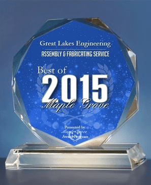
Great Lakes Engineering, Inc. Awarded 2015 Best of Maple Grove Award for Assembly & Fabricating Service

Great Lakes, MN - Great Lakes Engineering announced today that they are the latest recipient of the 2015 Best of Maple Grove Award in the category of Assembly & Fabricating Service.maple grove award

Each year, the Maple Grove Award Program identifies companies that they believe have achieved exceptional marketing success in their local community and business category. Great Lakes Engineering is a local company that enhances the positive image of small business through service to their customers and the community. “We are incredibly humbled and excited by this recognition,” commented Bruce Weaver, Owner at Great Lakes Engineering. “We strive to be a business with strong ties to the local community, and we are thrilled that the Maple Grove Award Program chose to honor our company with this achievement.”

Various sources of information were gathered and analyzed to choose the winners in each category. The 2015 Maple Grove Award Program focuses on quality, not quantity. Winners are determined based on the information gathered both internally by the Maple Grove Award Program and data provided by third parties. The Maple Grove Award Program is an annual awards program honoring the achievements and accomplishments of local businesses throughout the Maple Grove area. Recognition is given to those companies that have shown the ability to use their best practices and implemented programs to generate competitive advantages and long-term value.

To learn more about Great Lakes Engineering, call (763) 425-4755.

Great Lakes Engineering, Inc. Hires E-Tronix as Local Rep

Great Lakes, MN - Great Lakes Engineering announced today that they have hired E-Tronix to represent all of their products in the territory of Minnesota, North Dakota, South Dakota, Wisconsin, Illinois and Iowa.

“Great Lakes Engineering has a long history of providing great products, great service, and great knowledge to the world of surface mount technology,” commented Erik Stromberg, President of E-Tronix. “We’re very excited to have partnered with an industry leader like Great Lakes Engineering.”

E-Tronix is a Manufacturer's Representative Company that specializes in electronics assembly, medical device manufacturing, semiconductor manufacturing, and research and development industries.

e-tronix logo

To learn more about E-Tronix, email President Eric Stromberg at estromberg@e-tronix.com, or visit www.e-tronix.com.

To learn more about Great Lakes Engineering, call (763) 425-4755.

Great Lakes Engineering, Inc. Introduces the Wave Glide™ Innovative Squeegee Blade

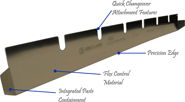
Great Lakes, MN - Great Lakes Engineering announces the introduction of the Wave Glide™, an innovative new Squeegee Blade developed by Lu-Con Technologies of Flemington, NJ, and designed to offer users a number of advantages over conventional squeegee blades.

wave guide squeegee blade

The Wave Glide™ Squeegee Blade is designed to be custom fit to any blade holder on the market today using slots, not holes, eliminating the need to completely dissemble the blade holder when the blade needs replacement.

Its unique Integrated Paste Containment Wing requires no setup or operator involvement, virtually eliminating paste tram-lines or paste seeping out behind the guides. No more tricky deflectors for operators to deal with that just end up getting removed and thrown away. The result - Less paste required for good printing results with users reporting paste saving of up to 250 grams per job! The Wave Glide™ Squeegee Blade is easy clean up as there are no nooks or crannies to contend with.

Simplicity and functionality wrapped up in one elegant design.

Detailed information about The Wave Glide™ Squeegee Blade can be obtained by contacting John Carr, Director of Sales at Great Lakes Engineering, Inc. at johnc@greatlakeseng.com.

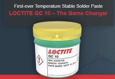
Great Lakes Engineering, Inc. Announces GAME CHANGER: First Ever Temperature Stable Solder Paste

Great Lakes, MN - Great Lakes Engineering announced today that they will be distributing a revolutionary solder paste. In what is a true market breakthrough, Henkel has developed the first ever temperature stable solder paste: LOCTITE GC 10. GC 10 is stable at 26.5 °C for one year and at temperatures of up to 40 °C for one month, providing benefits throughout the logistics and operations chain, while still offering unbeatable printability and reflow performance.

“We are extremely excited about this product,” commented Bruce Weaver, Owner at Great Lakes Engineering. “We have samples in several of our customer’s shops right now and it looks very promising. This will be a big deal in the solder paste world.”

solder paste

Some of the key aspects of LOCTITE GC 10 which separate it from other solder pastes are:

No Refrigeration

Removal of cold storage improves logistics efficiency and reduces shipping and warehouse costs. On the production line, no thaw period is required, allowing for immediate start-up.

Improved Stability

The main benefit of LOCTITE GC 10 is its stability. It is stable at the most extreme temperatures for extended lengths of time, yet still offers unmatched batch-to-batch consistency.

Improved Printing

Leading the industry in paste-transfer efficiency, LOCTITE GC 10 also delivers up to 24-hour abandon times, up to 72-hour stencil life and more than 95% on-line paste utilization.

Improved Reflow

Not only does LOCTITE GC 10 deliver the shiniest Pb-free solder joints in the industry, it also provides superior coalescence and wetting on long soak profiles, significantly reducing solder-related defects.

To learn more call (763) 425-4755